Schematic diagram of energy storage photovoltaic power generation V) generation and an overview of electrical storage technologies. The basic unit of a solar PV generation system is a solar cell, which is a P-N junction diode. It's more than just a drawing; it is a detailed plan that illustrates how every component connects and interacts to generate, store, and deliver power. For homeowners, installers, and DIY. . Understanding the circuit diagram of a PV system with storage is crucial for homeowners looking to make the leap, as it provides the blueprint for effective energy capture, storage, and utilization. Working Principle: The working of solar cells involves light photons creating electron-hole pairs at the p-n. . New energy storage cabinet schematic dia e System (BESS) connected to a grid-connected PV system.
[PDF Version]
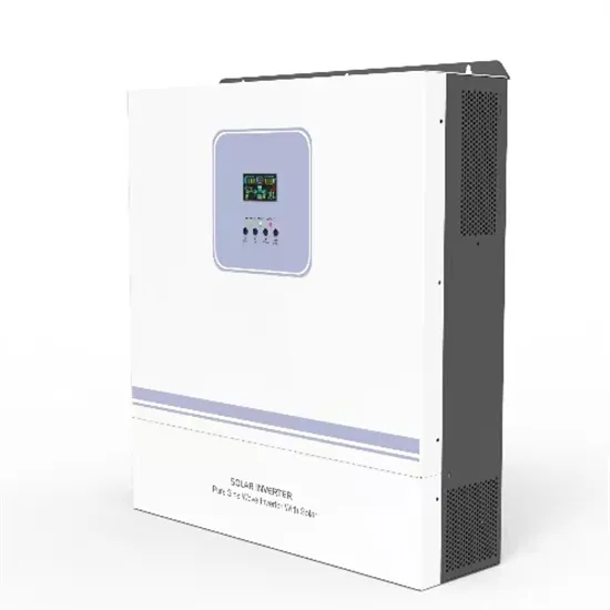
A conceptual power train schematic diagram below illustrates the principles of operation of a three-stage grid tie inverter. Such a topology can be useful for low-voltage inputs (such as 12V) in grounded systems. The control circuits and miscellaneous details are not shown. . Almost any solar systems of any scale include an inverter of some type to allow the power to be used on site for AC-powered appliances or on the grid. The available inverter models are now very efficient (over 95% power conversion. . In this article we discuss how inverters work, includ-ing string, or single-phase, and central, 3-phase inverters; explore major inverter functions, key components, designs, controls, protections and com-munication; and theorize about future inverter technology. Match the Inverter Size with Panel Output: The inverter. . Inverter in general is an electronic device that converts direct current (DC) voltage to alternating current (AC) voltage. On the other hand, the charge controller regulates the battery charging. These inverters are an essential component of grid-tied solar energy systems, allowing homeowners and businesses to generate. .
[PDF Version]
A lithium-ion battery diagram visually breaks down the core components and electrochemical processes of these ubiquitous energy storage devices. It typically highlights the anode (graphite), cathode (lithium metal oxide), separator, electrolyte, and current collectors. . This article will provide an overview on how to design a lithium-ion battery. It will look into the two major components of the battery: the cells and the electronics, and compare lithium-ion cell chemistry to other types of chemistries in the market, such as sealed lead acid (SLA), nickel-metal. . Resolution of these issues requires attention to both the circuit design and the printed circuit board (PCB) layout. Understanding a lithium-ion battery diagram provides insight into battery fundamentals, making it easier to troubleshoot issues or. .
[PDF Version]
The graph shown below represents the discharge characteristics (voltage versus charged percentage) of a typical 24 V lead acid battery, which has not been charged or had current drawn from it for few hours. Figure 1: Typical discharge curve (voltage versus % charge) for a 24. . A solar energy storage system diagram is the foundational roadmap for any successful solar power installation. It's more than just a drawing; it is a detailed plan that illustrates how every component connects and interacts to generate, store, and deliver power. . This example shows the design of a stand-alone solar photovoltaic (PV) DC power system with battery backup. eves 85% RTE in the beginning of the project.
[PDF Version]
Example simple Microgrid with library of PQ-based Renewables and Diesel GenSets. . Microgrids as the main building blocks of smart grids are small scale power systems that facilitate the effective integration of distributed energy resources (DERs). In normal operation, the microgrid is connected to the main grid. Coalition stakeholders include the City of Oakridge, South Willamette Solutions, Lane County, Oakridge Westfir Area Chamber of Commerce, Good Company/Parametrix, Oakridge Trails. . follows the schematic layout as in Figure 1. Then, using this simulation syste EFFICIENT MICROGRID SYST micro grid during 24 hours on a typical day. This particular example is used in "Part 3: Using Simscape Power Systems to Simulate Microgrids":. . GitHub - imranmehdi5511/Phasor-Microgrid-MATLAB: Simple microgrid examples that can be used for dynamic studies of interconnected DERs (such as wind, solar, diesel gensets and energy storage).
[PDF Version]
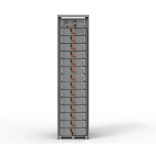
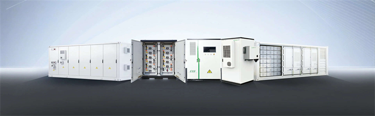
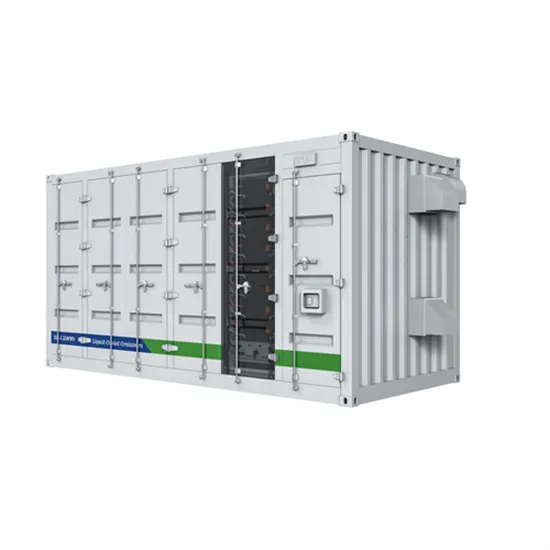
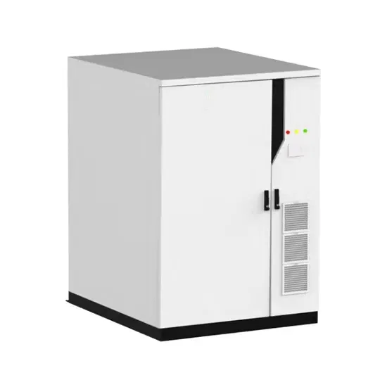
In this comprehensive guide, we will dissect the components of a battery energy storage system diagram, explore the differences between AC and DC coupling, and help you identify the right configuration for your commercial or residential needs. It's more than just a drawing; it is a detailed plan that illustrates how every component connects and interacts to generate, store, and deliver power. Some typical uses for BESS inclu e: Load Shifting - store energy when demand is low and deliver when demand is hi ttery energy storage systems (BESSs) are becoming a primary. . onents of a battery energy storage system (BESS). The battery comprises a fixed number of lithium cells wired in seri s and parallel within a frame to create a modu the inside and outside of. . The block diagrambelow represents AC Coupled Battery Energy Storage System solutionrecommended by onsemi. The system stores energy in an AC form which uses an inverter, providing flexibility and reliability. This guide is for: Anyone who's ever muttered "Why does my battery bank keep tripping?" We've structured this article like a proper electrical circuit - clear pathways, no unnecessary resistance.
[PDF Version]