Creating a compliant pv system single-line diagram (SLD) is a critical skill for any electrician working in solar. This diagram is the electrical roadmap of your photovoltaic installation, providing a clear, concise overview of the entire system for the Authority Having Jurisdiction (AHJ). . Experience from the field suggests that ground faults and arc faults are the two most common reasons for fires in photovoltaic (PV) arrays; methods are available that can mitigate the hazards. In this context, ABB. . Electrical systems should be drawn separate from other drawings such as architectural, structural, mechanical. This is a solar cell and the common symbols for it. PV systems and fire likelihood vs. Ground-faults in PV arrays could potentially result in large fault current which may increase the risk of fire hazards.
[PDF Version]
That plan is mapped out in a professional electric car charger home installation diagram, which acts as the blueprint for the entire project. Our diagrams illustrate: Wiring the circuit breaker in a single-phase 120/240V. . One essential aspect of EV charging is understanding the wiring diagram. It details the entire electrical path, protecting your vehicle, your home, and your family. This charging system includes several sub-assemblies that are considered vital in these machines.
[PDF Version]
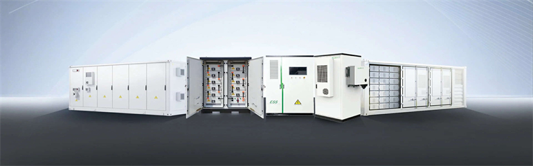
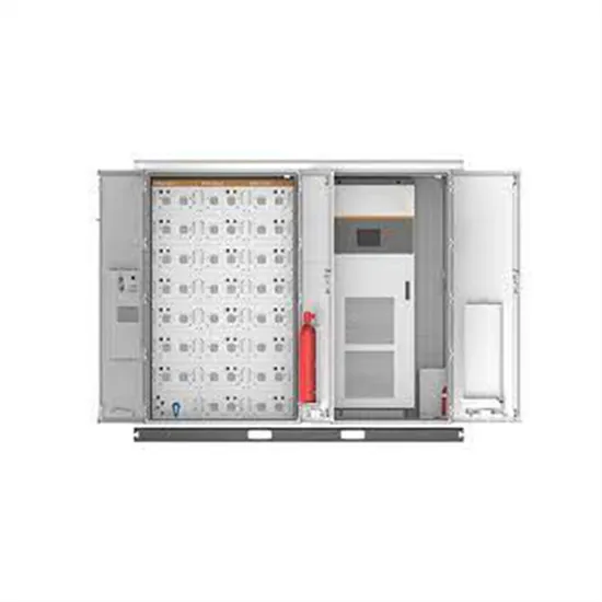
A detailed solar energy storage system diagram breakdown, explaining components, configurations, and design principles for achieving energy independence. . To achieve the ideal configuration and cooperative control of energy storage systems in photovoltaic energy storage systems,optimization algorithms,mathematical models,and simulation experimentsare now the key tools used in the design optimization of energy storage systems 130. What is the energy storage capacity of a photovoltaic system? Specifically,the. . The AES Lawai Solar Project in Kauai, Hawaii has a 100 megawatt-hour battery energy storage system paired with a solar photovoltaic system. Sometimes two is better than one. DC-DC converter and solar are connected on common DC bus on the PCS. Energy Management System or EMS is responsible to provide seamless integration of DC coupled energy storage and solar. For simplicity we draw a single phase system but the concept is applicable for three phase system with one (3-phase) or multiple inverters in parallel. For homeowners, installers, and DIY. .
[PDF Version]
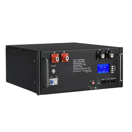
One-line diagram and layout/general arrangement of the conceptual microgrid solution(s). . Presentation was intended to build foundational understanding of energy resilience, reliability, and microgrids. Coalition stakeholders include the City of Oakridge, South Willamette Solutions, Lane County, Oakridge Westfir Area Chamber of Commerce, Good Company/Parametrix, Oakridge Trails. . Microgrids are localized electrical grids with specific boundaries that function as single controllable entities. This. . The process of disconnecting and later reconnecting to the grid is complex and specific to each microgrid project, and a document developed to aid in system design, called the Sequence of Operations, clarifies how a microgrid is intended to behave. In this article, we will define common modes of. . Alternate con guration for MPPTs capable of 2 x solar panel Imp. Non-Backed-up Loads • Up to 3 PowerPro (280AH) batteries per EG4 Hybrid Inverter can utilize internal bus bars with no need for external bus bars or fusing. 2 A microgrid can operate in either grid-connected or in island mode, including entirely off-grid. .
[PDF Version]
Provide an architectural drawing and riser diagram for the homeowner showing the planned location for future photovoltaic and solar hot water system components. Space requirements and layout for photovoltaic and solar water heating system components should be taken into account early in the design. . Photovoltaic bracket pad specifications and models table refers to all of the various components of a PV system beyond the actual modules. In general, photovoltaic composite structures are three-layer laminates with a thin soft core layer. Solar panel brackets are an ess ntial component of any solar panel system. The brackets are designed to withstand harsh weather conditions. . Let's face it – most DIY solar enthusiasts get starry-eyed about panels and inverters, then suddenly realize they're holding a photovoltaic bracket structure diagram size table that might as well be ancient hieroglyphics. In the event of a conflict between this manual and any code, the installer shall contact Solar F undations USA® supplied/specified. . Photovoltaic (PV) systems (or PV systems) convert sunlight into electricity using semiconductor materials. It can also generate electricity on cloudy and rainy days from reflected sunlight. PV systems can be designed as. .
[PDF Version]
This atlas is a schematic diagram for the installation of solar panels, and it includes the following parts: Please click this link to learn more Schematic diagram of PV roof layout. This atlas is a schematic diagram for the installation of solar panels, and it includes the following parts: Please click this link to learn more Schematic diagram of PV roof layout. ported by racking systemswhich come in two basic forms. The first is a mechanically fastened system and the second,th more common of the two,is a ballast restrained system. Tesla's power producing photovoltaic (PV) roofing Tiles are visually indistinguishable from the non-power producing metal or glass roofing Tiles, enabling homeowners the ability to harvest solar energy without aesthetic. . The following white paper provides recommendations on the structural design of roofing systems when considering solar panels. Solar power is produced by converting sunlight into electricity. DWG format available upon request. We wont get into any calculations, leave that to the professional engineers at Pure Power.
[PDF Version]