This repository provides the design, implementation, and analysis of a Single Phase Grid Connected Inverter. High-efficiency, low THD. . There are two main requirements for solar inverter systems: harvest available energy from the PV panel and inject a sinusoidal current into the grid in phase with the grid voltage. •The actual design criteria could include: specifying a specific size (in kW p ) for an array; available budget; available roof space; wanting to zero their annual electrical usage or a number of other. . The project emphasizes the use of renewable energy sources, particularly photovoltaic (PV) systems, and their integration into electrical grids. Cannot retrieve latest commit at this time. The design is associated to the STEVAL-ISV003V1 demonstration board which demonstrates the possibility of implementing a full microinverter. .
[PDF Version]
Pressing the reset button usually fixes most inverter problems. If that does not work, the battery may be low and needs to be recharged. . My understanding is that I need to hook a wire from my inverter to the correct hookup in my fuse box (see pictures) and it's as simple as that? I believe the original owner had a wire already running from the fuse box to where our batteries are. We'll. . The inverter serves as a power conversion device, taking the direct current (DC) power stored in batteries, solar arrays, or vehicle systems and transforming it into the alternating current (AC) electricity required to run standard appliances and electronics. This mechanism is what enables off-grid. . ⚡ Did your circuit breaker keep tripping or a fuse keep blowing? You might have a dangerous short circuit. Before beginning any work, carefully read all safety instructions, and always observe them w en working on or with the inverter. The installation must follow all applicable national g future operation and maintenance.
[PDF Version]
The solar inverter circuit diagram typically includes components such as solar panels, a charge controller, batteries, and an inverter. A solar power inverter is an essential part of a solar power system as it converts the direct current (DC) generated by solar panels into alternating. . So, in this tutorial, we will make the “PV Solar Inverter Circuit diagram. Please be aware that the various appliances or electronics in your home run on AC, not DC. The solar panel power is either directly used for operating the inverter or it's used for charging the inverter battery.
[PDF Version]
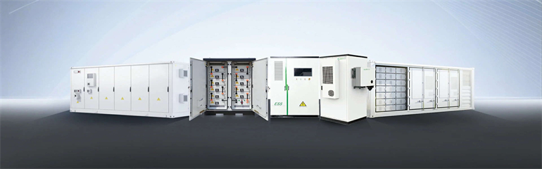
A typical circuit board architecture includes the following key subsystems: DC input interface and EMI filter module, DC-DC boost converter (for non-microinverter systems), DC-AC inverter bridge, MPPT control module, gate drive circuit, voltage/current sensing. . A typical circuit board architecture includes the following key subsystems: DC input interface and EMI filter module, DC-DC boost converter (for non-microinverter systems), DC-AC inverter bridge, MPPT control module, gate drive circuit, voltage/current sensing. . An inverter circuit is an electrical circuit that converts DC current into AC current to power appliances and devices in everyday life. Inverter circuits have experienced rapid development, especially in the last two decades, along with the increasing use of solar power systems as a clean. . When a DC to AC inverter is operated through a solar panel, it is called a solar inverter. The solar panel power is either directly used for operating the inverter or it's used for charging the inverter battery. Please be aware that the various appliances or electronics in your home run on AC, not DC. There are five stages of this Circuit: This PV Solar Inverter Circuit. . This comprehensive technical article dives deep into the engineering essentials of solar inverter circuit board design, offering a detailed exploration for electrical engineers and hardware designers.
[PDF Version]
A solar string inverter is easy to understand. It connects to a group of solar panels,called a 'string'. AC is what we use in our homes and send to the grid. Otherwise, disconnect is not required (per the NEC, but may be required per the utility). What wiring is needed for s ther in series or. . For many new to photovoltaic system design, determining the maximum number of modules per series string can seem straight forward, right? Simply divide the inverter's maximum system voltage rating by the open circuit voltage (Voc) of the module used and you're good. ” The string inverter has been the most common. . ) LOWEST EXPECT AMBIENT TEMPERATURE BASED ON ASHRAE MINIMUM MEAN EXTREME DRY BULB TEMPERATURE FOR ASHRAE LOCATION MOST SIMILAR TO INSTALLATION LOCATION.
[PDF Version]
Tutorial and DIY overview of digital multimeter (DMM) usage for solar power enthusiasts. Topics include diagnosing DC-AC inverter direct short, open circuit, resistance check, diode check, checking battery pack voltages, cell voltage, BMS status. Plus general troubleshooting and t. It confirms the inverter's input and output accuracy. We will walk you through each step, from essential safety precautions to detailed diagnostic procedures, ensuring you have the knowledge and confidence to troubleshoot your inverter. . Summary: Learn how to accurately measure voltage and current in inverters for solar systems, industrial applications, and residential energy storage. Why Measuring Inverter Voltage Matters Inverters are. . Based on real PV installation scenarios, the following five multimeter measurement techniques cover nearly all high-frequency operations at solar project sites and can significantly improve safety and diagnostic accuracy. Now, measure the current of the panel by connecting your multimeter.
[PDF Version]