What Is A Solar Inverter?Solar Inverter Circuit DiagramWorkingComponentsThe circuit diagram shown above illustrates a solar inverter using the SG3525 PWM controller IC. Here''s an explanation of how the circuit works: In this circuit diagram, the push-pull topology of DC to DC converters is used to convert a DC voltage source into an AC voltage. A step-up transformer is used to increase the voltage from 12 volts to 220See more on microcontrollerslab hilelectronic
Solar Inverter Control Boards Manufacturing and
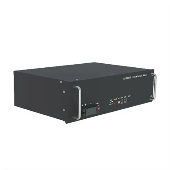
Designed to manage high-power currents generated by solar panels, these PCBs regulate energy flow in systems ranging from small inverter circuit boards to
View Details